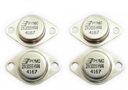

Low base to emitter voltage, makes it easily switchable even with nominal output potentials available from linear ICs without incorporating buffer stages.High collector to emitter voltage handling capability makes it highly versatile for most power amplification applications.Rugged design and packaging, makes it less vulnerable to mechanical stresses during procurement and transportation.The device has become particularly popular due to some of its outstanding features, as summarized below: The basic application range include power switching, high fidelity amplification, shunt regulation, and forming the output stages of various power circuits.

Other capacitances should be negligible for your use.The 2N3055 is a NPN Epitaxial-Base Planar Transistor that normally comes encapsulated in a metal Jedec TO-3 package. Although the IRLU8726 would probably be a lot cooler.Īs stated a small gate resistor might be a good idea for PWM use to reduce current draw from the MCU a bit, the value of 150ohms seems okay and is not critical, use something between 150 and 470 and you should be fine. With an ambient of 20C, that would give a temperature just under 70C which should be quite safe at that current where the maximum allowable case temperature is about 155C. 77W at 10A which will mean a rise in temperature of about 48C degrees C over ambient. With an R DS ot 0.077ohms will give about. The dissipation would be the IRL540 should work but it will get a little hot. Hi dc42, no offense intended here, but I think you made a little error on the math.

Look for a mosfet with much lower Rds(on), such as IRLU8726PBF (0.008 ohms max). IRL540 is not a good mosfet to use for switching 10A, its Rds(on) is 0.077 ohms max so it will dissipate around 7.7W when carrying 10A. With Faraday's law, the delta-T is in the denominator, so the less time it takes for the magnetic field to collapse, the higher the voltage is. The energy is the same, the "delta-T" is much smaller. The SAME energy (less losses) that you put into the rubber band stretching it is returned when you release it, but because it's faster, the "snap" stings your skin. When you let go of the top, the rubber band will snap DOWN (negative) very fast. Say you hold the bottom of the rubber band and stretch the top end higher and higher (more and more "positive"). So, normally the diode does nothing (reverse biased), But if an inductive kickback occurs, the diode is forward biased and "snubs" the spike. the PWM goes to the "off" cycle), the magnetic field collapses and can generate hundreds to thousands of volts in the OPPOSITE direction. So, if you put +12 volts into the motor, when you de-energize it (i.e. Faraday's law basically says that the faster a magnetic field changes, the higher the voltage induced in the wire. When the current is removed, the magnetic field collapses almost instantly. When the motor is energized, a magnetic field forms on the armature. What the diode does is protect the 2N3055 from inductive kickback. The resistors you highlighted are not necessary. What should be the values?Īlso: what is the functionality of the 1N4007 diode next to the motor? And do I need to put another diode from the collector to the emitter of the 3055? I don't know if I need the two green resistors (with question marks), I didn't use them in the test but I saw that some people use them. The circuit works but I'm not sure that is perfectly ok. In the picture you can see that I'm using a 2n2222 that controls a TIP3055 (or a 2N3055).
How to use 2n3055 transistor full#
I need to control the speed of a dc motor (0.5 A no load, to 10 A full load).


 0 kommentar(er)
